·Some details are not shown. Please refer to specification sheets for all information.
R5-NC2
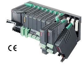
Remote I/O R5 Series
CC-Link INTERFACE MODULE (CC-Link Ver.1.10; for 32-point analog signals)
MODEL: R5-NC2[1]
ORDERING INFORMATION • Code number: R5-NC2[1] Specify a code from below for [1]. (e.g. R5-NC2/Q) • Specify the specification for option code /Q (e.g. /C01)
[1] OPTIONS blank: none /Q: With options (specify the specification)
SPECIFICATIONS OF OPTION: Q COATING (For the detail, refer to M-System's web site.) /C01: Silicone coating /C02: Polyurethane coating /C03: Rubber coating
RELATED PRODUCTS • PC configurator software (model: R5CON) Downloadable at M-System’s web site. A dedicated cable is required to connect the module to the PC. Please refer to the internet software download site or the users manual for the PC configurator for applicable cable types.
GENERAL SPECIFICATIONS Connection CC-Link: Euro type connector terminal (Applicable wire size: 0.2 – 2.5 mm2 (AWG 24 to 12), stripped length 7 mm) Internal bus: Via the Installation Base (model: R5-BS) Internal power: Via the base (model: R5-BS) Isolation: CC-Link to internal bus or internal power RUN indicator: Bi-color (green/red) LED; green in normal communications; red when receiving (Function selected with DIP SW) ERR indicator: Bi-color (green/red) LED; the green ON/ blinks in communication errors; red when transmitting (Function selected with DIP SW) Data allocation: Fixed to Mode 2
CC-Link COMMUNICATION Transmission cable: Approved for CC-Link CC-Link: Conforms to Version 1.10 Station address: Rotary switch; 1 – 64 Station type: Remote device Number of occupied stations: 8 (This module incorporates two (2) ASICs for four (4) stations (32 I/O, 16 words) to handle 32-word data. Two (2) remote device stations for four stations each must be assigned for this module to the host PLC.) Baud rate setting: Rotary switch 156kbps, 625kbps, 2.5Mbps, 5Mbps, 10Mbps
INSTALLATION Operating temperature: -10 to +55°C (14 to 131°F) Operating humidity: 30 to 90 %RH (non-condensing) Atmosphere: No corrosive gas or heavy dust Mounting: Installation Base (model: R5-BS) Weight: 100 g (3.53 oz)
PERFORMANCE Insulation resistance: ≥ 100 MΩ with 500 V DC Dielectric strength: 2000 V AC @ 1 minute (CC-Link to internal bus or internal power)
STANDARDS & APPROVALS EU conformity: EMC Directive EMI EN 61000-6-4 EMS EN 61000-6-2 RoHS Directive EN 50581
EXTERNAL VIEW
COMMUNICATION CABLE CONNECTIONS
TRANSMISSION DATA DESCRIPTIONS The DIP SW located at the side of the module must be turned OFF except at SW3. Data Allogcation Mode 2 is used for the R5-NC2. In this mode, two (2) words are assigned for one I/O module regardless of whether the second word area is required or not. For example, discrete I/O modules require only one (1) word, but two (2) words are automatically assigned to these modules. ■I/O CAPACITY A maximum of 16 I/O modules can be mounted per station.
I/O DATA DESCRIPTIONS The data allocations for typical I/O modules are shown below. Refer to the manual for each module for detailed data allocations.
EXTERNAL DIMENSIONS unit: mm (inch)
SCHEMATIC CIRCUITRY & CONNECTION DIAGRAM Note: In order to improve EMC performance, bond the FG terminal to ground. Caution: FG terminal is NOT a protective conductor terminal.


 VPGD: Số 9, Ngõ 523/82/3 Minh Khai, Tổ 28D, P. Thanh Lương, Q. Hai Bà Trưng, TP. Hà Nội.
 Hotline: 0971961212

